Push-pull control cable assemblies are more common than you might think. Also known as control cables, push-pull control cables are found virtually everywhere. Have you used a lawn mower? They’re in the choke, which is the part of the mower that regulates fuel flow and ultimately, powers to the mower’s blades. Everyone has used a bicycle, right? Well, push-pull cable assemblies control slowing and stopping using the bike’s handbrake systems. Push-pull control cables also manage how cyclists shift gears. Aircrafts use them too; they’re in the rudder and vertical stabilizer.
So, as one can see, push-pull cables are in many of the products and conveyances we use in our daily lives, but often take for granted.
What is a push-pull cable?
Push-pull cables, or control cables, are types of mechanical cable assemblies that are used to translate motion and force across any distance, directing such actions through pushing or pulling. Take, for example, rudders on an aircraft. Control cables are used to change the position of the rudder, changing the aircraft’s yaw, which is its rotation across a vertical axis.
However, if your mechanical system requires a push-pull cable assembly, a lot could go wrong, which is why it is paramount that you consult with your design engineers before developing and later, purchasing a push-pull cable assembly. While design concerns are many, among the most important are the system’s application specifications, which deal in such things as the “who, what, when, where, how and why?” Design specifications address variables such as cable tolerance, or what kind of casing is appropriate. Lastly, what your push-pull cable assemblies need to achieve addresses the physical science behind how the control cable system will (or will not) work.
Push-Pull Cable Application Requirements
Circling back to the bicycle example, handbrake cables twist and turn from the handlebars, down along the frame, ultimately ending near the brakes and the tires. Such meandering through the bicycle is an example of features that need to be considered when applying the cable to your mechanical system. These considerations are examples of what goes into the application specifications of a push-pull cable assembly.
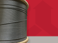
Among the first consideration deals in whether the application requires a push-pull or pull-pull control cable assembly. For example, the choke in the lawn mower is a push-pull cable assembly. Push-pull control cables usually have a stiff cable, such as the 1x7 cable construction, which comprises seven monofilaments. Alternatively, a solid core wire will suffice in some applications as well. This is typical of light-duty assemblies, like a lawn mower.
Conversely, a pull-pull cable assembly is different story.
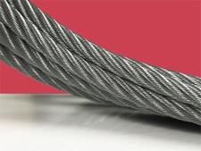
A bicycle’s handbrakes are quite possibly the best-known pull-pull application among those discussed so far. Pull-pull applications require a flexible cable, usually made with larger constructions than their push-pull counterparts, such as a 7x7 mechanical cable, which is made from 49 monofilaments. It’s critical to comprehend, however, that an increased monofilament count does not necessarily equate to increased tensile strength in some applications.
Browse our push-pull components

Push-Pull Control Cable Considerations
Some other important push-pull control cable assembly application considerations include cable flexibility, environmental conditions and size. Most push-pull cable assemblies will be required to achieve multiple bend radii. But, if your control cable is too rigid, it risks bird caging, which is the physical separation of monofilaments from one another. The wrong control cable may also experience kinking too as it navigates tight radii. Additionally, environmental factors are crucial in achieving the best possible lifespan for the push-pull assembly. Is the control cable system going to reside outdoors or indoors, for example? Environmental conditions inform what materials should be used to maximize durability when exposed to particulates and other potentially harmful artifacts that could damage moving parts. Furthermore, cable size, which would be determined by the load and bend radii requirements of your application, needs to be similarly scrutinized.
Typical control cable applications include affecting chokes and dampers. Push-pull cable assemblies are actually ideal for this type of application because push-pull control cables are designed to transmit motion across a distance. In addition, equipment used to open and close doors, activate fire suppression mechanisms, engage safety brake devices and power throttle cables are also common use cases for push-pull control cables. Control cable assemblies are highly popular in the aerospace industry as well. As a matter of fact, hurdling through outer space coming in August of 2022, will be NEA Scout, an asteroid-seeking satellite that uses a bus-sized solar sail that is deployed by one of Sava’s control cables.
Push-Pull Control Cable Design Specifications
Have you ever heard the Gaelic proverb, “measure twice, cut once?” Well, the careful design of your push-pull control cable assembly is an essential part of your application’s success. While application specifications scratch the surface of what the design specifications strive to achieve, this is where things get technical.
Most control cables comprise the following fundamental components.
- Core Cable or Solid Wire
- Conduit
- Fittings
Push-Pull Core Cable
Take the core cable to start. The diameter and construction of the core cable is what determines the assembly’s load capacity, which is naturally the most important design specification for control cables. Afterall, if your cable doesn’t support the load requirement, something downstream is going to fail. Depending upon on the load, Sava push-pull core cables range in diameter from 0.015” to 0.09375”.
The simplest core for a push-pull control assembly is a solid wire, which is ideal for applications involve minimum bending. To achieve greater flexibility however, you can substitute a stranded cable for the solid wire, which helps to facilitate routing through the conduit. Furthermore, if the application requires that force be applied in a pull direction only, stranded mechanical cables have an easier time achieving tighter bend radii.
The core cable of a control assembly is mainly constructed with stainless or galvanized steel, although other alloys can be used. Additionally, control cable assemblies can come with or without fittings, which is determined by other mitigating application specifications.
Push-Pull Cable Conduit
Once you have established the appropriate core cable for the application, the control cable assembly’s conduit guides the cable along its path. The simplicity of such a design concept is rooted in the fundamental physical science fact that, given any number of ways to transmit motion, motion always seeks the path of least resistance. The conduit routes the cable without the assistance of mechanical systems, such as links or pulleys, by virtue of painlessly traversing the interior of the conduit. Take for example bicycle handbrakes. The bends in handbrake assemblies involve mechanical cable winding around the bike frame with only the conduit to assist its smooth movement. In this scenario, nothing is supporting the movement of the cable through the conduit except for the pull action of the operator.
The conduit also prevents the cable from buckling and dirtying, which is why it is push-pull cable assemblies are not lubricated. Lubricants attract debris that can clog the control cable’s path and prevent the cable from fluidly sliding back and forth as it is pushed and pulled through the conduit.
What’s more, the interior lining of the conduit must also be carefully studied too. Conduit is ideal in applications that require less friction and repeated fluid motion. This permits the seamless translation of push and pull forces across the core cable.
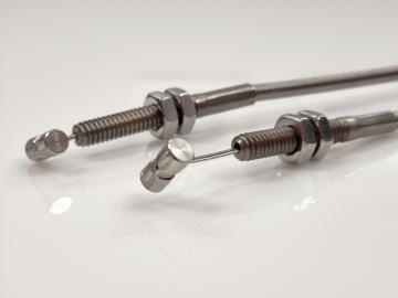
Fittings
Once the push-pull cable conduit and core cable have been decided upon, an industrial press applies cable fittings to one or more areas of a push-pull control cable assembly. Fittings are mechanical components, pressed or swaged to the mechanical cable, that allow an assembly to be attached to mating parts, or installed into a larger motion control system.
Core Solid Wires
While not fittings, core solid wire can be formed into shapes, such as a centered loop, an offset loop, a U-bend, Z-bend or L-bend. The formed solid wire terminates the push-pull cable assembly system and is usually oriented in a way that allows for the wire to smoothly mate with receiving components.
Core Cables
Fittings can be swaged or pressed onto a core cable or solid wire, and can include balls, stop sleeves, ball-end plugs, threaded plugs, loop sleeves and many others. Similarly, to core solid wire, which, as discussed, can be formed, cable fittings are also applied to the push-pull cable assembly to ensure seamless pairing with mating parts.
Cable Conduit or Casing
Some fittings, known as terminals, are used to simply clamp or attach the conduit to or near the control system. To name a few, a clamp terminal or wire clamp are attached to the conduit, which is then installed on a surface to hold the conduit in place. Conversely, other terminals, such as bulkhead terminals, can be directly applied to the ends of the conduit, pairing the control cable assembly to receiving components in the system.
Making Tight Radii
In addition to conduit and fitting considerations, how well your push-pull cable system makes its way around bend radii is of the utmost design importance as well.
The bend radii, and subsequently the lifespan of the cable, are bound together. The bend radii should not be too tight or too large to best maximize the life and efficiency of control cable assemblies. Tighter bends can be a root cause of reduced service life because of additional friction between the core cable and the conduit. On the other hand, too wide of a bend and it could take longer to achieve a distance traveled.
The recommended radii vary between 2” and 8”, dependent on the conduit size and construction of the core cable. It is critical to note that lighter conduits, combined with lighter loads, increase flexibility. On the contrary, heavier conduits, with heavier loads, increase rigidity.
Load Capacity
Load capacity is naturally one of the most important design considerations for push-pull cable assemblies.
Design engineers must determine if the load applied is push, pull or both in nature. In situations requiring pushing, design engineers must ensure that the cable and fittings avoid buckling. In situations that require pulling, design engineers must consider stroke length, which loosely translated, is the amount of cable movement within a conduit and the subsequent stretch of the cable.

Physical Science
Just as everything in the world has fundamental science behind how it works, so do push-pull control cable assemblies. However, understanding the physical implications of a naturally performing push-pull control cable assembly mitigates the risk of application failures after deployment.
Accordingly, the distance traveled by the cable, within the conduit, should be kept to a minimum, since increased travel length increases friction and decreases output. It is therefore advisable that all travel be kept at 5” or less, and the linear speed of operation low.
Lost Motion
In addition to keeping travel at a minimum, lost motion can be achieved in many ways, so it is important to know how to mitigate unwanted movement of the cable as well.
Backlash
Backlash is a concept of lost motion that is caused by the cable moving within the conduit with a change in direction of motion. Mathematically, backlash occurs when the core cable's OD is too small for the ID of the push-pull casing or conduit, which leaves play between the cable and the interior walls of the casing. This play causes a loss of motion, which will contribute to the premature failure of the assembly in the field. Minimizing the quantity of bends in the control cable system to only that which is necessary reduces the potential of backlash.
Buckling
Buckling occurs under a compressive load. When a control cable is pushed through the conduit, compression is applied to the cable. The conduit protects the cable from buckling, allowing the push force to be smoothly translated to the end of the system. The conduit’s walls also prevent the cable from damage, such as fraying or snapping. Contrarily, when a pull force is applied to the control cable, the system is in tension, which eliminates the risk of buckling.
Input Load Factor
There is a simple mathematical formula that shows that friction between the cable and the conduit causes a loss in output force for a certain amount of input force. This is expressed with the ratio of input force to output force, I = P * F, which is the Input Load Factor, where the I is the input load, the P is the output load, and the F is the input load factor.
Graphed against friction, which is described in these scenarios as the degrees of bend in a system, you can calculate the input load factor accordingly. For example, consider the following:
It is likely clear by now that push-pull control cable assemblies have many benefits, including the fact that they are virtually maintenance-free. However, as is also evident, perfecting a push-pull cable assembly is laden with potential points of failure if not designed properly.
Makers of these elegant push-pull components should collaborate on their push-pull control cable design engineers to ensure common challenges are avoided. Carl Stahl Sava Industries is an industry leader in the design and manufacture of push-pull control cable assemblies. Contact our design engineers to make a more informed decision and to begin designing your control cable assembly solution today.